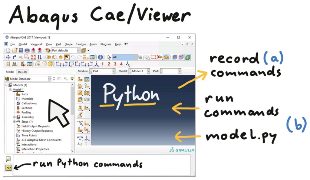
Now let’s look at how to script a model in Abaqus CAE! All your clicks in Abaqus CAE are regarded as Python commands in the background. You can also write such commands yourself and run them in Abaqus CAE, building up your model automatically.
We can obtain those Python commands from the reference guide in the Abaqus documentation, where all Python commands are listed and explained. Since we already know how to use CAE and do not know how Abaqus calls all its Python commands, it is more convenient to record commands of what we are doing in Abaqus CAE. And then look up their detailed options in the documentation anduse them to build up our scripted Abaqus model.
I) Recording and Running Python Commands
How to record Python commands from clicking in Abaqus CAE and how to run Python commands in Abaqus?
a) Recording Python commands from Abaqus CAE
When clicking in Abaqus CAE, the corresponding Python commands are automatically written to the abaqus.rpy file in the active directory. Everything is recorded in this file, even if you scroll or zoom into the model or do evaluations.
At the time you save your Abaqus model, two files are saved: First, the actual CAE (.cae) file that you can open with Abaqus CAE, and second, the journal file (.jnl) where commands crucial to the model generation are recorded. So, actions like zooming and evaluations in the Viewer are not recorded.
Furthermore, you can start recording a macro in Abaqus with File/Macro Manager >> create, Directory=work. This starts writing commands to the abaqusMacros.py file until you click Stop Recording.
In the Student Edition of Abaqus, both the
.rpyand the.jnlrecording are disabled, which leaves you with the Macro Manager. If you have a full version of Abaqus, I suggest using the.jnlfile for building the model and the.rpyfile for the evaluation.
b) Running Python code in Abaqus CAE
How can we now run Python commands in Abaqus CAE? The first option is clicking on File/Run Script. There, you have to select a python file to be run in Abaqus.
The second option to run Python commands in Abaqus is the so-called Kernel Command Line Interface. This is the frame at the bottom of the CAE window that you can reach by clicking on the >>>-symbol. Here, you can run single commands or multiple lines of Python code. It is best for testing new commands and playing with Python. This command line also helps you with writing code: If you press the UP key, you get to the last executed command and pressing the TAB key auto-completes your commands.
The third option is starting Abaqus CAE from the Windows or Linux command line and stating a Python script that is then run in CAE. This can be done either by opening the Abaqus CAE window (script=...) or just opening CAE in the background (noGUI=...):
abaqus cae script=model.pyCode language: Python (python)abaqus cae noGUI=model.pyCode language: Python (python)From recorded commands a script for the model can be developed. In many cases, you can just copy your model together from those commands, but for some of them, you can’t. The trickiest commands concern selecting entities such as edges, faces, and cells. For such selections, the most convenient commands are not recorded. Also, they make it necessary to understand how the Abaqus Python commands are organized, so we look into that now.
II) Python in Abaqus CAE
As already mentioned, Abaqus CAE has a Python-kernel running in the background, with objects similar to the modules (models, parts, materials, etc.) you already know from Abaqus CAE . To work with those Abaqus objects, you need to import them:
from abaqus import *
from abaqusConstants import *
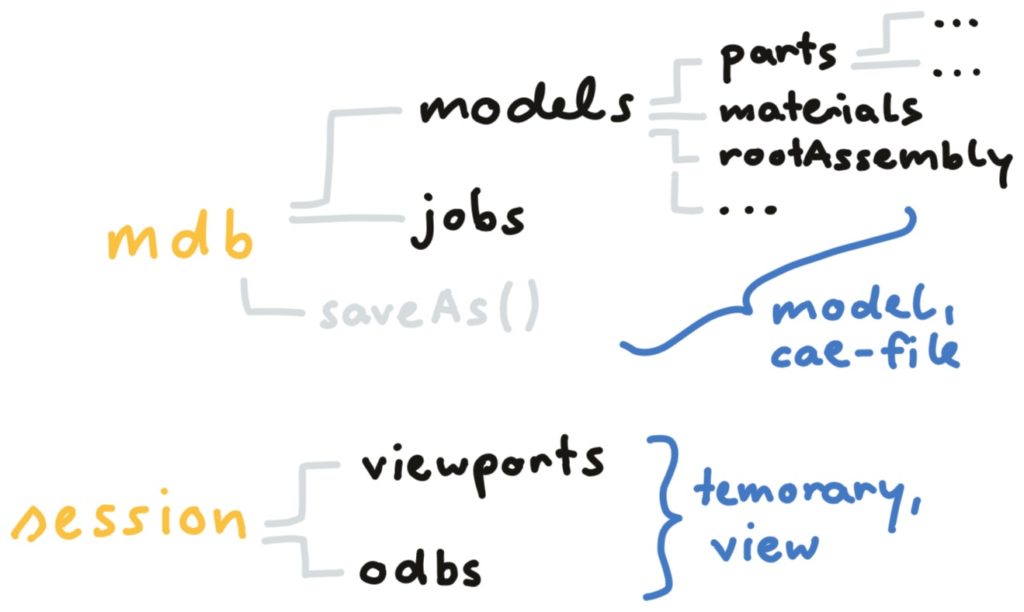
from caeModules import *Code language: Python (python)There is a hierarchy of Abaqus objects: Everything builds on the two repositories mdb (Model Database) and session (CAE window and view). You have imported mdb and session by writing from abaqus import *. The model database mdb has the sub-object models, that itself contains the parts, materials, etc. which itself contain geometry, nodes, and so on.
Let’s look at the object models. You can create a new model with the command mdb.Model(). Such commands for creating models, parts, etc. are called constructors and are written with a capital letter. In the brackets of a constructor, you can pass along more information, in this case, the name of the new model:
mdb.Model(name='test-model')Code language: Python (python)This constructor creates an instance of the class models with the name test-model. We can access this instance by writing:
mdb.models['test-model']Code language: Python (python)When writing commands in the Abaqus Command Line, you can use TAB to auto-complete your lines. If you have already written
mdb.models[and you press TAB, Abaqus suggests a model name. If you press TAB again, it suggests the next option. Also if you writemdb.Model(and then TAB, you get the options of this function.
When creating a model, you can write m = mdb.Models(name='test-model') to use the variable m instead of writing mdb.models['test-model'] each time you need it. The command mdb.models also works as a Python dictionary, so you can use the .keys() and .values() functions to see what models exist:
>>> mdb.models.keys()
['Model-1', 'test-model']Code language: Python (python)
Then you can create a part in this model and then a reference point in this part and so on. To list all the methods of your model m, mdb, session, or an instance, you can use the dir-command:
>>> dir(mdb)Code language: Python (python)I do not list the output here, because it is too long. Look for yourself in Abaqus! These methods can change the object or create a new instance. There are not only constructors and sub-classes, but also functions that do something. For mdb, there is the function saveAs(path) that saves your model under the path that you state in the brackets:
>>> mdb.saveAs('test.cae')Code language: Python (python)Now you know the Abaqus object hierarchy: The model database mdb contains models and jobs, the models contain parts, materials and so on. This will help us now when we look into creating sets and surfaces that contain such objects.
III) Sets and Surfaces
For a nice and clean Abaqus CAE model, it is important to create sets and surfaces first using meaningful names and then apply constraints, boundary conditions, and loads on those.
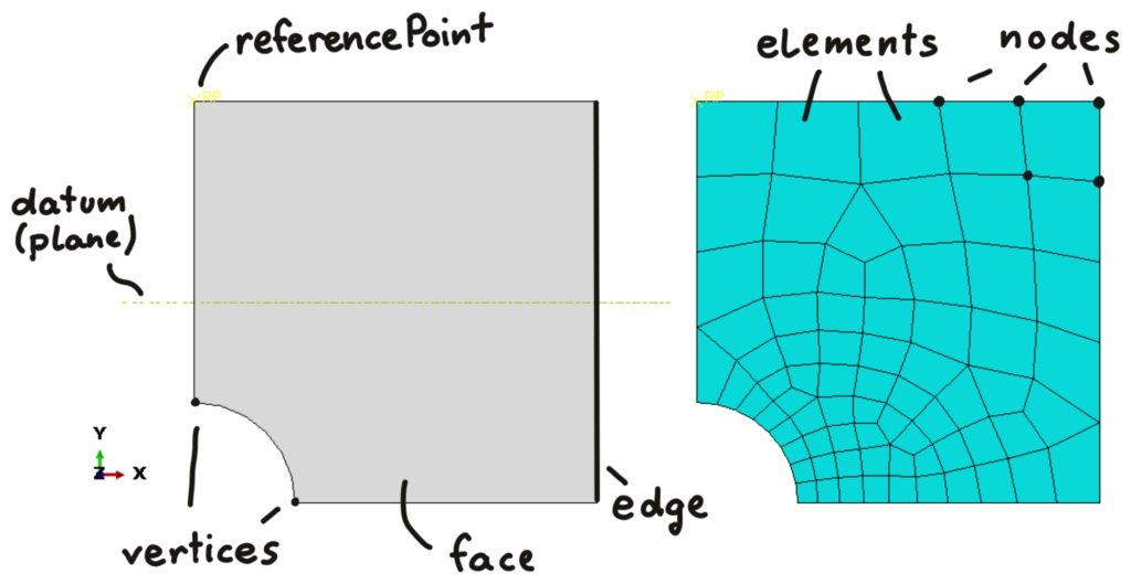
Sets can contain anything (vertices, edges, faces, cells, datums, referencePoints, nodes or elements)
Surfaces can contain edges in 2D models and faces in 3D models. They are used to define contact and surface-based loads or constraints.
So let’s look at how we can create sets and surfaces in a scripted way. First, we look into edges to understand the basic principles of automated selection. Then, we see how that can be extended to faces, cells and other entities.
a) Selecting Edges
We first look at how to handle edges in Abaqus CAE using Python commands. Then we look at how to select other entities like vertices, faces, cells, datums, referencePoints, nodes, and elements. In the figure below, we see that there are two data types for edges: A single edge (Edge) or edges (Sequence of Edges). Every edge has an index and every edge is also uniquely identified by a point on it (pointOn).
Recording commands for edge selection
If you have a part in Abaqus CAE and you record the commands for creating a set that contains one edge of the part, you get a line like that (p is the part variable defined by p = m.parts['Part-Name']):
p.Set(edges=p.edges.getSequenceFromMask(('[#400 ]',),),
      name='Set-1')Code language: Python (python)
So we create a set from edges that we provide during the set creation. More details on what the set needs are stated in the Abaqus Documentation. The edges are provided in a weird way with a mask command and a certain number which is 400 in this case:
p.edges.getSequenceFromMask(('[#400 ]',),)Code language: Python (python)That does not help us much for our automated model: We do not know what the mask #400 means and by using this number we might select something different of the model once we scripted the model.
Selecting edges usingfindAt
There is also no easy way for knowing what mask string (like #400) to use for what edge. This is why we already had a certain command in the model.py template, where we adapted the journalOptions of Abaqus CAE:
session.journalOptions.setValues(replayGeometry=COORDINATE,
        		         recoverGeometry=COORDINATE)Code language: Python (python)
After running that command one, the recorded set creation commands of Abaqus CAE will use findAt statements instead of the unpractical getSequenceFromMask statements we saw above:
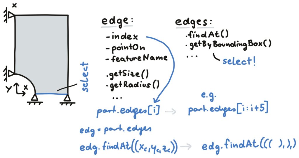
p.edges.findAt(((20.0, 10.0, 5.0), ))Code language: Python (python)Now that looks better for scripting! We obviously just need to write a coordinate that lies on the edge in three brackets. Just make sure that the coordinate does not have multiple edges on it because then you will just get one of them, and you do not know which one upfront. Multiple edges work similarly:
p.edges.findAt(((20.0, 3.4375, 20.0), ), ((20.0, -16.25, 5.0), ),
               ((20.0, -9.6875, 0.0), ), ((20.0, 10.0, 5.0), ))Code language: Python (python)
Do we need three brackets or would two also work? Well, for that question, we need to look at the data types in Abaqus. When we write a findAt command like above, we get a sequence of edges (that we can also get by using a range of indices in square brackets like p.edges[2:4]) and not just a single edge. In a set or surface we do need a Sequence of edges:
# multiple edges
>>> type(part.edges[1:5])
<type 'Sequence'>
# one single edge
>>> type(part.edges[0])
<type 'Edge'>Code language: Python (python)
Writing
p.edges[:]gives you all the edges in the part in a sequence.
If you have a list of coordinates that you want to use in findAt, you need to pass the list as coordinates:
list_edge_pos = [[20.0, 3.4375, 20.0],[20.0, -16.25, 5.0],
                 [20.0, -9.6875, 0.0], [20.0, 10.0, 5.0]]

p.edges.findAt(coordinates=list_edge_pos)Code language: Python (python)
A list like that could have been created automatically from positions of edges that you know from your model parameters, so this command could be something to use in a scripted model.
Selecting edges using getByBoundingBox
Sometimes we want to create sets from multiple edges that lie at specific coordinate ranges in the model. If we have a symmetry plane it would be nice to just select all edges that lie in this plane, no matter how many of them there are. This can be done with the function getByBoundingBox(). You can use xMin, xMax, yMin, etc. to specify a region. All edges that completely lie in this region are selected. Due to the tolerances in Abaqus, using xMax=0 might not give you all edges that lie at x=0, so you should define a very small tolerance value and use that:
TOL = 1e-5

# all edges that lie at x=10
p.edges.getByBoundingBox(xMin=10.-TOL, xMax=10.+TOL)

# all edges that lie at x=0 (if no edges lie at x < 0)
p.edges.getByBoundingBox(xMax=TOL)Code language: Python (python)
Now that is much more elegant than findAt, isn’t it? I use it for all simple selections and in most cases, the combination of getByBoundingBox and boolean set operations is sufficient. There are similar functions that use a cylinder or a sphere instead of the box for selection. You can check them out in the Reference Guide of the Abaqus Documentation.
There are boolean operations (union, difference, intersection) for existing sets that are handy: With
pdefined as a part we can write (replace the keyword UNION by DIFFERENCE or INTERSECTION for the other operations):p.SetByBoolean(name='Set3', sets=(p.sets['Set1'],p.sets['Set2'],), operation=UNION)
Selecting edges by edge properties
For some edges, it would be rather complicated to calculate a coordinate that lies on the edge. With defining a bounding box, we often would also select other edges that we do not want. So it would be nice to select an edge by other properties. In the above figure, we saw that each edge has a featureName (a string that defines how it was created) and functions like getSize and getRadius. Maybe you have some edges that you know exactly the size of but not where they are: So let’s look at how to select those! You can check out all the properties of single edges by looking at one edge in your part:
>>> dir(p.edges[0])Code language: Python (python)So there is getSize(), which obviously returns the edge length, there is the featureName() functions and other functions like getCurvarture(). You can try them and also look into the reference guide to learn details about them.
There is no function for directly creating sets from edge properties. We can, however, get the edges we want by those features, then create a list of edge positions (with the function pointOn for each edge), and use those positions in a findAt command. If you use a for loop, that could look like that:
edge_coord = []

for edge in p.edges:
    if edge.getSize() > 5.-TOL and edge.getSize() < 20.+TOL:
        edge_coord.append(edge.pointOn)

p.Set(name='e1', edges=p.edges.findAt(coordinates=edge_coord))Code language: Python (python)
Or if you use list comprehension like me, you can write the selection in one line. See which one you prefer and then stick to it:
edge_coord = [edge.pointOn for edge in p.edges if
              edge.getSize()>5.-TOL and edge.getSize()<20.+TOL]

p.Set(name='e1', edges=p.edges.findAt(coordinates=edge_coord))Code language: Python (python)
The set e1 then contains all edges in the model that have a size between 5 and 20. In some cases, that is easier than using findAt or other functions for selection.
By all means, do not call your edge sets e1, this is just to not make the code to long in these blocks. Use meaningful names, it will save you a lot of worries!
b) Selecting other model entities
Everything that we have seen for selecting edges also works for vertices, faces, cells, nodes, and elements. Just note that the properties would be different: A vertice, for example, wouldn’t have a size! So use findAt and getByBoundingBox, and if you want to select something by its properties, take one of those and use dir() to see the properties.
For datums (planes, axes, coordinate systems, etc.) and reference points, it actually is different. When you pass a referencePoint (a separate model node to be used for coupling, rigid bodies, connectors, etc.) to a set, Abaqus wants you to use the following syntax:
# create referencePoint in part at coordinate (0,0,0)
p.ReferencePoint(point=(0,0,0))

# create set out of referencePoint
p.Set(name='RP', referencePoints=(p.referencePoints[3],))Code language: Python (python)
with 3 being the id of the reference Point that might also change when we change our model in the script. There might be some reasons why this has to be so complicated that I don’t get, but this is that rather inconvenient way you have to use referencePoints in sets:
# create referencePoint in part at coordinate (0,0,0)
rp = p.ReferencePoint(point=(0,0,0))

# create set out of referencePoint
p.Set(name='RP', referencePoints=(p.referencePoints[rp.id],))Code language: Python (python)
You would need a datum to partition a geometry. This would look like that:
# create a datum plane at x=5
plane = p.DatumPlaneByPrincipalPlane(offset=5, principalPlane=YZPLANE)

# partition all faces by the datum plane
p.PartitionFaceByDatumPlane(faces=p.faces[:],
                            datumPlane=p.datums[plane.id])Code language: Python (python)
Exercises
- Run this Python code in Abaqus CAE and look at all the functions the model and the part have.
- Try all the ways for selecting edges that were described above. See for yourself what happens when you select an edge with
findAtby giving a coordinate that belongs to two edges! You can check what a set contains by double-clicking on it in Abaqus CAE. - Create a reference point in your part and make a set out of it. Look at the recorded Python commands and see what id your referencePoint is.